This tutorial will teach you how to use the I/O ports on an AVR microcontroller. I will be using an Atmega8 but the general principles apply to any AVR microcontroller.
Introduction
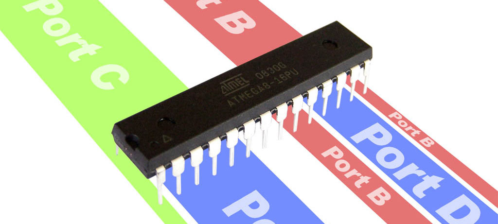
The Atmega8 has 23 I/O ports which are organised into 3 groups:
- Port B (PB0 to PB7)
- Port C (PC0 to PC6)
- Port D (PD0 to PD7)
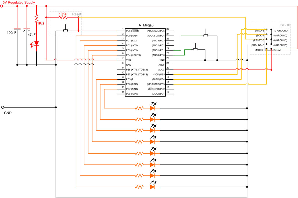
These are shown on the pinout diagram below.
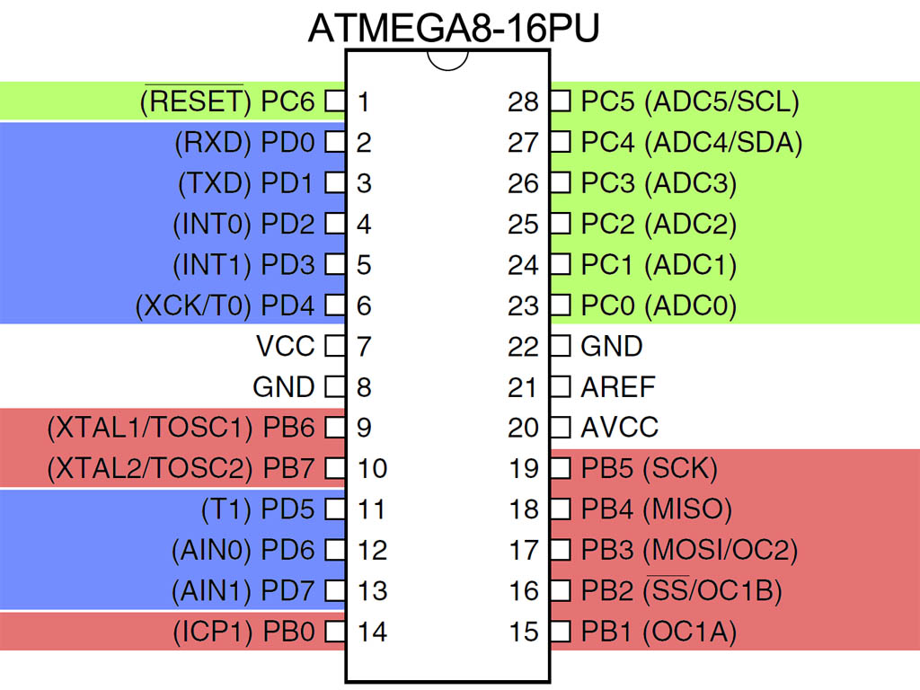
All of the I/O pins have secondary functions. These are shown in parenthesis on the pinout diagram.
PC6 is almost always used as a reset pin and is not normally available for I/O. PB6 and PB7 are often used for external crystal oscillators but not in this tutorial.
Port Registers
The following Registers are used for reading and writing to the I/O ports.
| Register | Type | Description | Notes | ||||||
|---|---|---|---|---|---|---|---|---|---|
| DDRB | Read/Write | Port B Data Direction Register | 1=output, 0=input | ||||||
| PORTB | Read/Write | Port B Data Register | |||||||
| PINB | Read only | Port B Input Register | |||||||
| DDRC | Read/Write | Port C Data Direction Register | 1=output, 0=input | ||||||
| PORTC | Read/Write | Port C Data Register | |||||||
| PINC | Read only | Port C Input Register | |||||||
| DDRD | Read/Write | Port D Data Direction Register | 1=output, 0=input | ||||||
| PORTD | Read/Write | Port D Data Register | |||||||
| PIND | Read only | Port D Input Register | |||||||
Each of these registers are 8 bits wide, with each bit (with the exception bit 7 of the Port C registers) corresponding to a single pin.
For the code examples I will be using binary literals. Consider the following code block.
1 2 3 | PORTD = 0b11110001; PORTD = 0xF1; PORTD = 241; |
Each line is doing the same thing. In each case a literal value is being assigned to PORTD. In the first case the value is being expressed in binary, in the second it is being expressed as Hexadecimal and in the last case it is being expressed in decimal.
The rightmost bit (least significant bit) represents pin 0 of port D (PD0) whilst the leftmost bit (most significant bit) represents pin 7.
Output
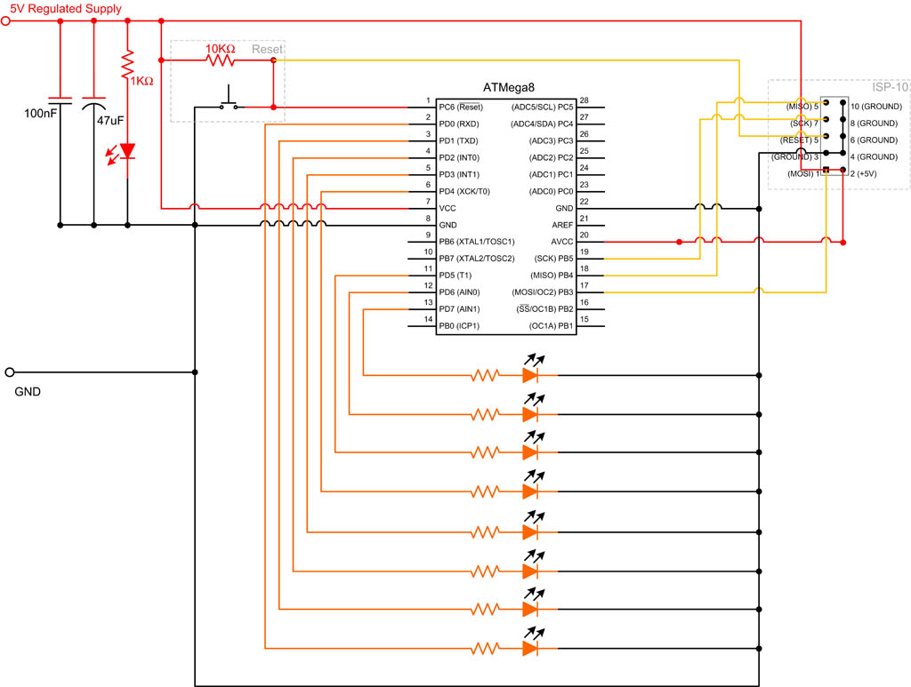
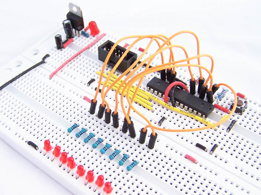
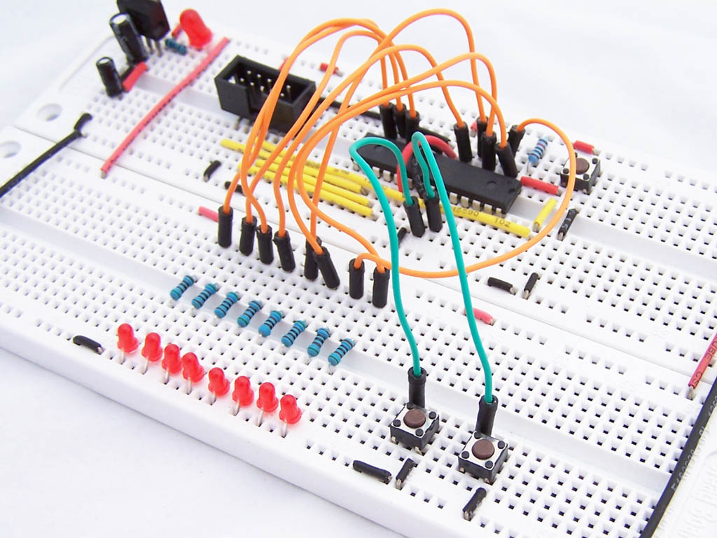
Let’s start by building a circuit with 8 LEDs connected to the Port D pins.
To use these pins as outputs, we need to set the Data Direction Register pin values to 1. A value of 1 is used for output whilst 0 is used for input.
DDRD = 0b11111111; |
Next we set the value of PORTD. Each bit is either a 1 or a 0 depending on whether we want the output to be on or off. i.e. 0 is off and 1 is on. so
PORTD = 0b00110001; |
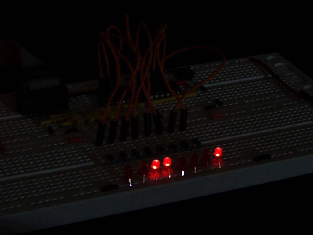
Will produce the following pattern in our LEDs
_BV and bitwise operators
When programming AVR devices, you often need to address single pins. The _BV macro and bitwise operators come in handy here.
_BV is a macro that takes a value between 0 and 7 and returns an 8 bit value with a “1” in the position nominate by the input parameter. So
- _BV(0) gives you 0b00000001
- _BV(3) gives you 0b00001000
_BV(i) is equivalent to 1 << i
The C programming language includes a set of bitwise operators which apply logic operations to individual bits. These can be combined with _BV to control individual pins. Consider the following code example.
PORTD = PORTD | _BV(3); // Turn PD3 on PORTD |= _BV(3); // Same as previous statement, but using compound assignment operator instead PORTD &= !_BV(3) // Turn PD3 off |
To learn more about bitwise operators, please refer to http://en.wikipedia.org/wiki/Operators_in_C_and_C%2B%2B#Bitwise_operators.
3 different ways to create a sweep pattern
Using what we have learned so far, consider 3 different implementations of a sweep pattern
1 2 3 4 5 6 7 8 9 10 11 12 13 14 15 16 17 18 19 20 21 22 23 24 25 26 27 28 29 30 31 32 33 34 35 36 37 38 39 40 | void sweep1() { PORTD = 0b10000000; _delay_ms(100); PORTD = 0b01000000; _delay_ms(100); PORTD = 0b00100000; _delay_ms(100); PORTD = 0b00010000; _delay_ms(100); PORTD = 0b00001000; _delay_ms(100); PORTD = 0b00000100; _delay_ms(100); PORTD = 0b00000010; _delay_ms(100); PORTD = 0b00000001; _delay_ms(100); PORTD = 0b00000000; } void sweep2() { for (int i=7;i>=0;i--) { PORTD = _BV(i); _delay_ms(100); } PORTD = 0b00000000; } void sweep3() { PORTD = 0b10000000; for (int i=0;i<8;i++) { _delay_ms(100); PORTD >>= 1; } } |
Input
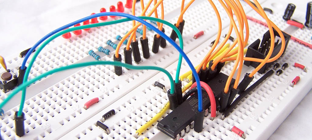
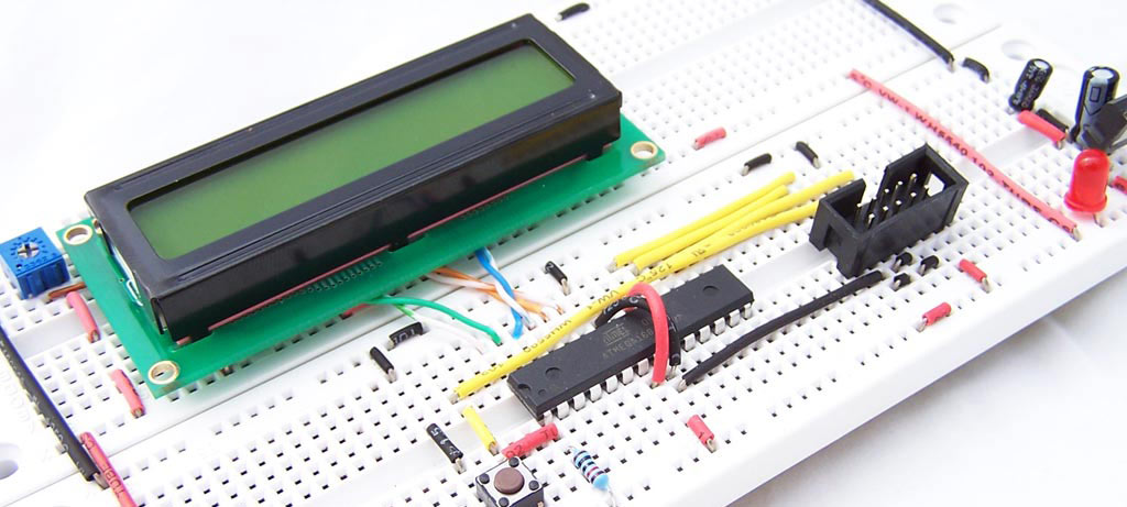
For the next section we will add 2 buttons to PC0 and PC1 as shown in the schematic and photo below.
To use these button you need to set the Data Direction Register values to 0 and the Data Register values to 1.
1 2 | DDRC = 0b11111100; // set PC0 & PC1 to input PORTC = 0b00000011; // set PC0 & PC1 to high |
By setting the PORTC values to 1, we are telling the microcontroller that this are held high. You will notice on the schematic above that when the buttons are pressed these pins go to ground. An alternative approach would have been to hold the lines low by setting the PORTC values to 0 and connecting the buttons to VCC.
To read the input values we look at the Input Register. In this example we look at PINC. A value of 1 for a given bit means the switch is open (not pressed) and a value of 0 means that it is being press.
We are now ready for some code.
1 2 3 4 5 6 7 8 9 10 11 12 13 | #include <avr/io.h> int main (void) { DDRD = 0b11111111; // All outputs DDRC = 0b11111100; // set PC0 & PC1 to input PORTC = 0b00000011; // set PC0 & PC1 to high while(1) { PORTD = PINC; } } |
In this example the LEDs will show you the state of the PINC input register. The 2 rightmost LEDs should be on, and will go off when each button is pressed.
Addressing Individual Pins
Using bitwise operators we can test if an individual button is pressed
if ((PINC & _BV(0))==0) //if button on PC0 is pressed { blink_3_times(); } if ((PINC & _BV(1))==0) //if button on PC1 is pressed { sweep(); } |
This is a bit convoluted. An easier and more readable way is to use the bit_is_set or bit_is_clear macros. Refer to http://www.nongnu.org/avr-libc/user-manual/group__avr__sfr.html for documentation for these macros.
1 2 3 4 5 6 7 8 | if (bit_is_clear(PINC,0)) //if button on PC0 is pressed { blink_3_times(); } if (bit_is_clear(PINC,1)) //if button on PC1 is pressed { sweep(); } |
The final program
Using what we have learned up to this point, we can now write the following program.
1 2 3 4 5 6 7 8 9 10 11 12 13 14 15 16 17 18 19 20 21 22 23 24 25 26 27 28 29 30 31 32 33 34 35 36 37 38 39 40 41 42 | #include <avr/io.h> #include <util/delay.h> void blink_3_times(void) { for (int i=0;i<3;i++) { PORTD = 0b11111111; _delay_ms(250); PORTD = 0b00000000; _delay_ms(250); } } void sweep() { PORTD = 0b10000000; for (int i=0;i<8;i++) { _delay_ms(100); PORTD >>= 1; } } int main (void) { DDRD = 0b11111111; // All outputs DDRC = 0b11111100; // set PC0 & PC1 to input PORTC = 0b00000011; // set PC0 & PC1 to high while(1) { if (bit_is_clear(PINC,0)) //if button on PC0 is pressed { blink_3_times(); } if (bit_is_clear(PINC,1)) //if button on PC1 is pressed { sweep(); } } } |

for the first code example you have – in the 3rd sweep in line 38 – did you mean PORTD >> i , as opposed to PORTD >> 1
?
Firstly the operator being used is >>= This is a combination of assignment and right shift. so
PORTD >>= 1 is equivalent to
PORTD = PORTD >> 1
each time me iterate through the loop, we want to move the 1, 1 position to the right. So we start with:
10000000
then have
01000000
00100000
00010000
00001000
00000100
00000010
00000001
If we right shifted by i we would have
10000000 initial value
10000000 i=0
01000000 i=1
00010000 i=2
00000010 i=3
and so on…