A few hacks to make bread boarding easier…
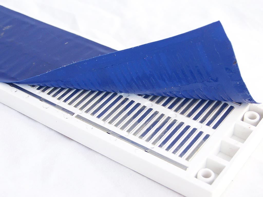
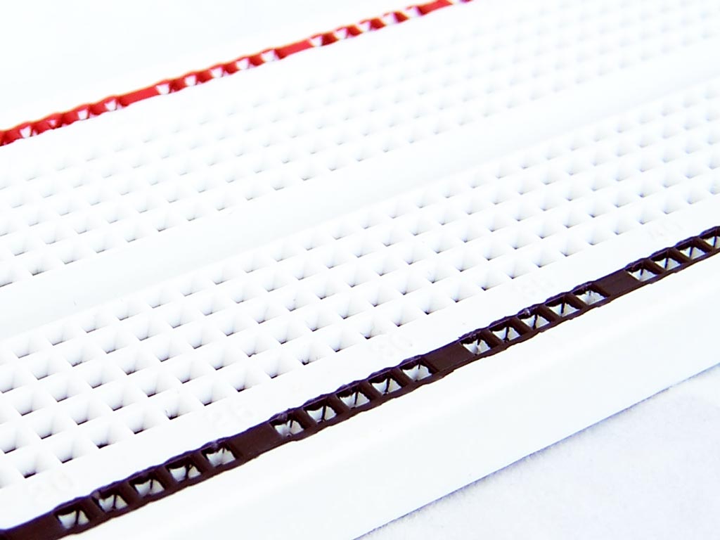
1. Hacking the power buses
The power buses on a breadboard are constructed in multiple pieces. To get continuity down the length of the bus you need to add jumper “staples” like so.
With this hack, we peel back the adhesive tape on the back of the breadboard, then thread some wire to connect the metal strips together. I used 24 AWG wire from a cat5 cable.
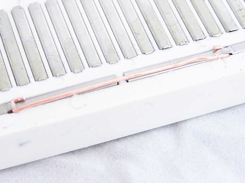
Alternatively just use self adhesive copper strips. i.e. The stuff that has conductive adhesive and is used to repair circuit boards.
2. Fun with colors
This one is pretty simple. Just get your permanent marker out and color in the positive and ground power buses.
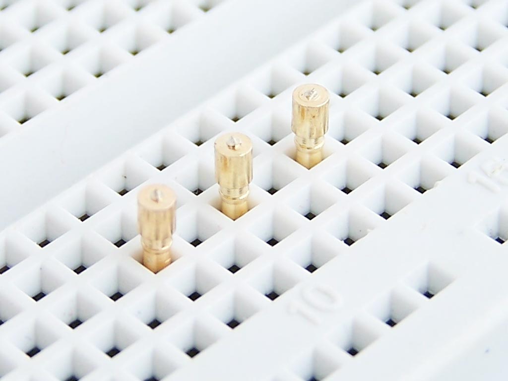
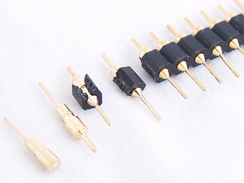
3. Gold test points
“Everywhere, the glint of gold”
These test points are made from a set of Swiss Machine Headers
Just cut the metal pins away, then take the shorter end off.
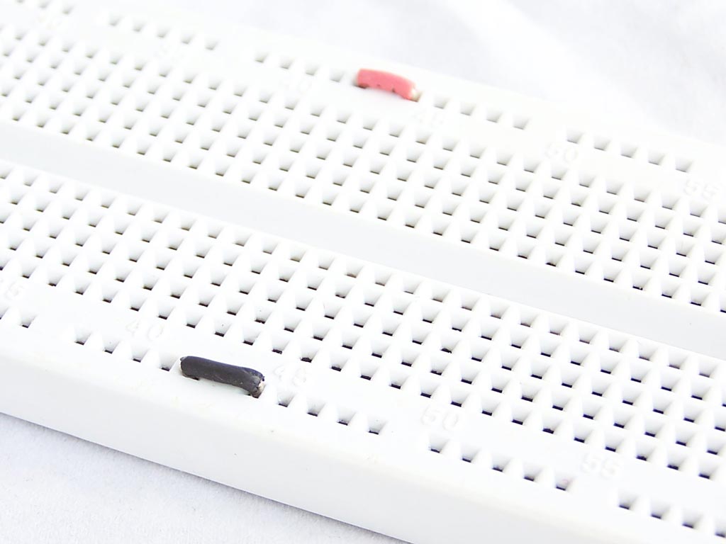
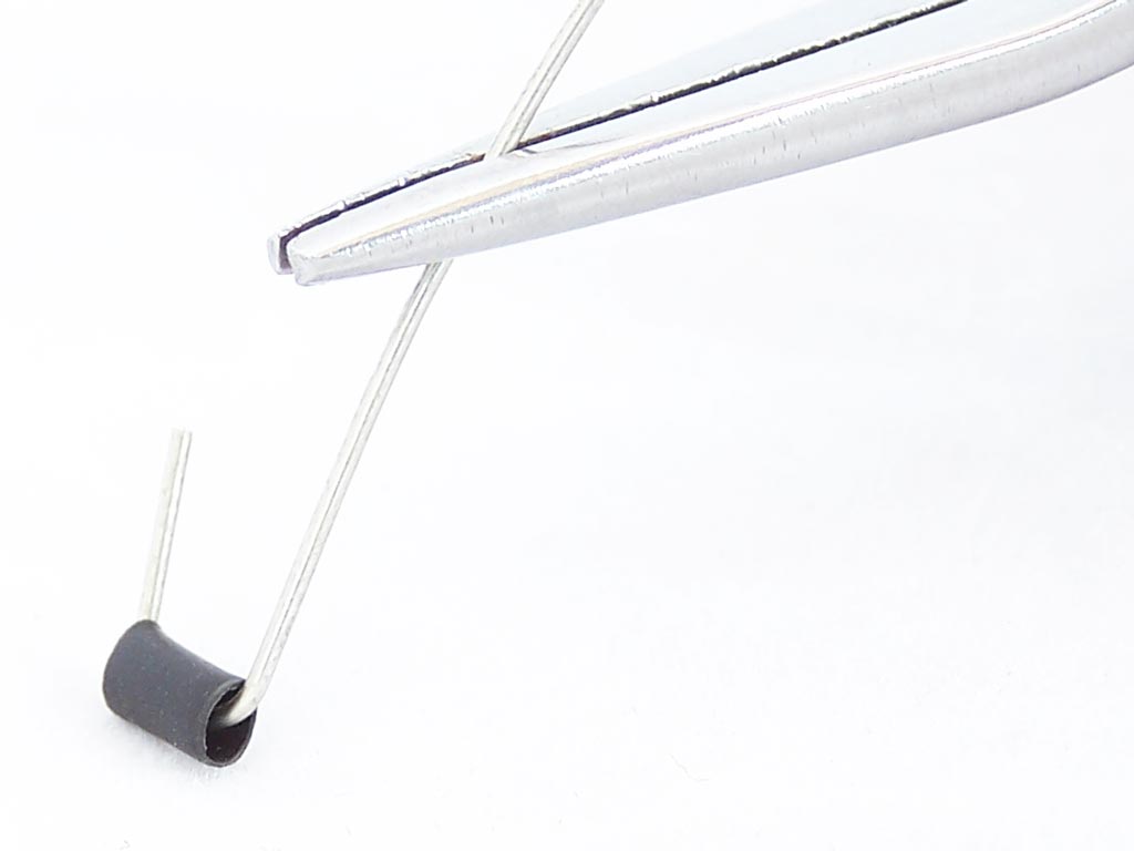
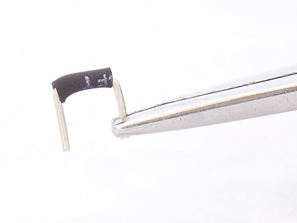
4. Make your own staples
These “staples” are used to bridge small distances on a breadboard.
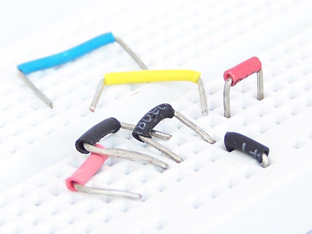
Constructed of 22 AWG wire and some heat shrink tubing, they are very easy to make.
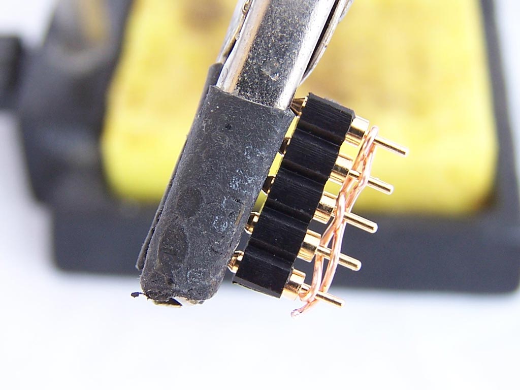
5. Swiss Machined Combs
There are times when you need to connect a bunch of tiepoints together. For example you may need to ground multiple pins on an IC. These “combs” make the job easier.
Simply solder a piece of wire across the top of the header, then cut the excess off.

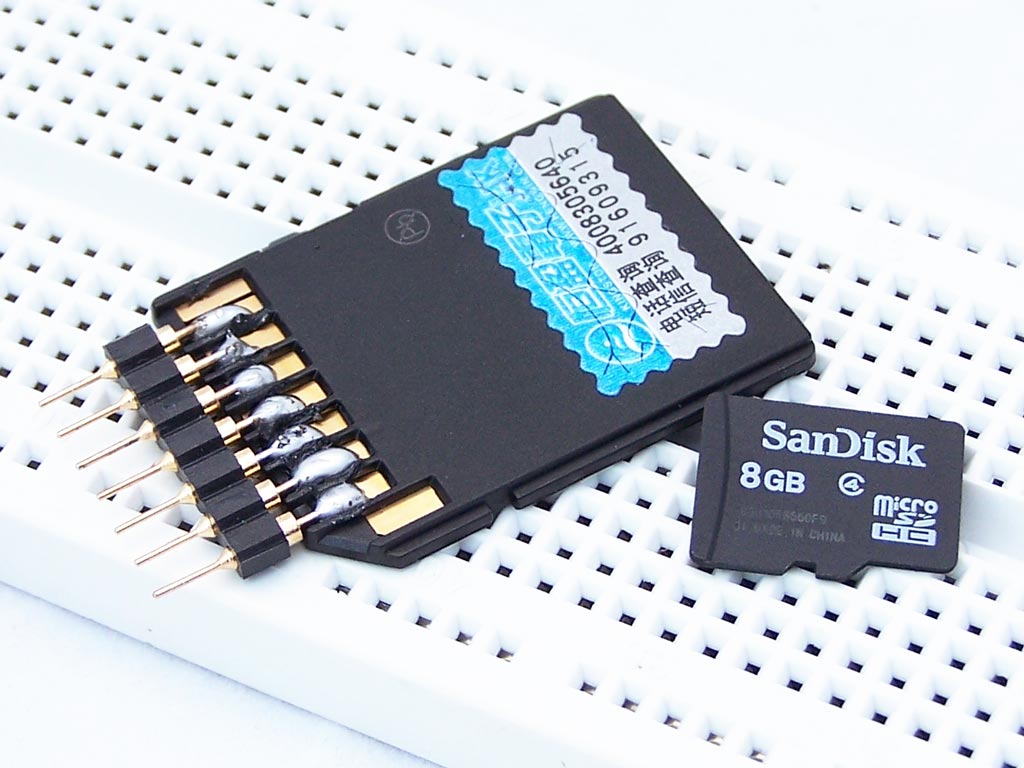
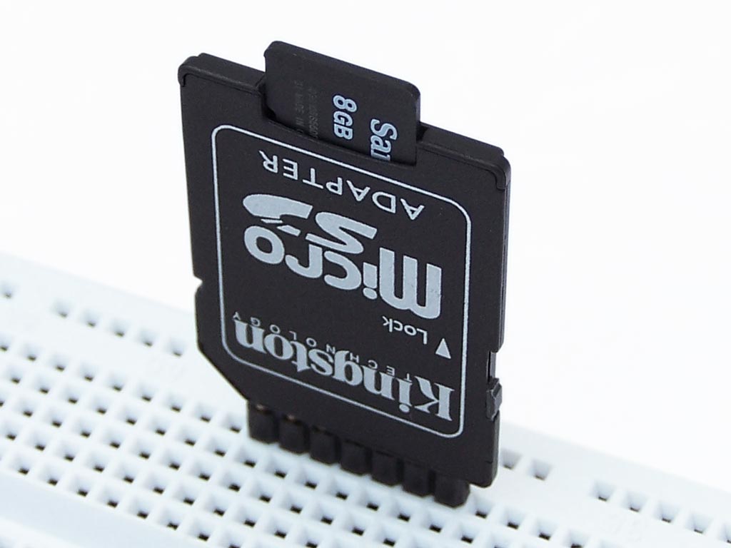
6. Getto micro-sd socket
Feel like playing with micro-SD cards?
Just use a micro-SD to SD adapter and solder some pins to the bottom. I used swiss machine headers because they are easier to insert than standard square headers.
The SD card has 9 connectors on the back, but for many applications only 7 are needed.
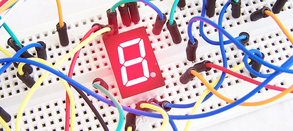
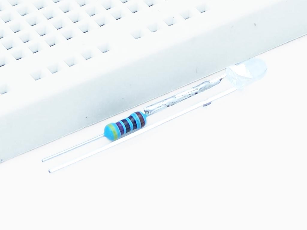
7. My LED joined the resistance
This LED has a resistor on the lead making it easier to use.
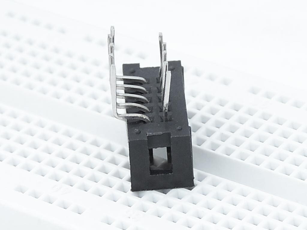
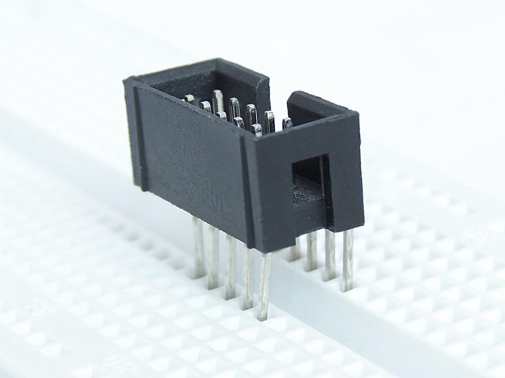
8. Hacking an IDC connector
IDC connectors don’t work well with breadboard because the rows of pins are too close together. With this last hack we use a right angle IDC connector and bend the pins so they fit.
Simple but clever. What did you put on the end of the alligator clip in part 5? It looks useful for holding headers and other such things without being too much of a heat sink.
It’s called “helping hands”. The one I have is similar to this one http://mightyoaktrading.com/store/index.php?main_page=product_info&products_id=333 but I took the magnifying glass off it. I find it just gets in the way.
I think that is heat shrink tubing. Great for not marring parts with the jagged edges of alligator clips, plus the rubber texture makes up for the lost friction.
Yes, it is heat shrink tubing.
“Just cut the metal pins away, then take the shorter end off.”
Or don’t take the shorter end off, because I can’t tell what the rationale for that is and it seems like you could use it as a mini-gripper connection point…
True. I was thinking it exposes a nice fat head which in easier to put probes on.
Wow, this is really great. I’m in an electronics class @ college right now, and this has given me a few ides. ^.^
I really like the LED+resistor, but I’m wondering, how do you know what resistors to hook up with LEDs? I always hear people telling me to do it, but I have idea what resistors to use. o.O
Personally, I use a 1k as a standard. Since it is just for testing/debugging, it doesn’t have to be perfect. 1k gives enough room for even up to 20V. Of course, if you’re always using 5v or 12v, you could use something more like 200 or 500. Just remember that it is just for testing/debugging, so it doesn’t have to be perfect.
Read up on Ohm’s Law (E=I*R). In this case we want to determine R, so we rearrange the equation to become R=E/I. Your LED’s data sheet should tell you the LED’s forward current and voltage, for example, 30 mA and 3V. This means you want to calculate your resistor so that 30mA flows through it and into the LED. Let’s say you’re driving the LED and resistor with a 5V signal. When the LED is turned on, it uses 3V of the 5V, which means you’ll have 2V across the resistor. Now, to determine the size of the resistor, you’ll substitute 2V for E and 0.030A for I. Thus, R=2/0.030, which is 66.67 ohms. This is most likely not a standard size for resistors, so find the next largest standard size. Don’t go for the smaller size, as it will allow more than the recommended current through the LED.
“Your LED’s data sheet should tell you the LED’s forward current and voltage, for example, 30 mA and 3V.”
This is what I was looking for. I’m quite familiar with Ohm’s law but I wasn’t sure how to know what the LED’s forward current/voltage should be.
Love these tips. I’ve done the SD Card one and the heat-shrink on the helping hands thing. Very inventive.
You’ve just made me learn a lot of practical breadboarding stuff. Thanks a lot!
The SDCard and led with resistor were just great discoveries. Thanks.