
Back in 2011 we wrote a tutorial on how to use Pulse Width Modulation to change the colour of an RGB LED. This part of the workspace project is based on the same principles, but on a larger scale.
Overview
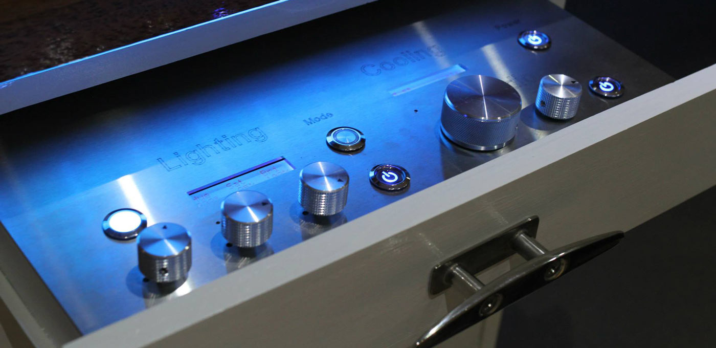
The RGB Lighting Controller allows you to control the colour and brightness of LEDs using a slide out control panel. The colours are controlled by hue, saturation and brightness controls and you can also switch it into Slow Cycle, Fast Cycle, Slow Pulse, Fast Pulse and Strobe modes. In reality I don’t really use many of these modes, I just got carried around when building the controller.
The system comprises of the following components:
- Control board, built with a 28 Pin AVR Development Board and ATMega168A Microcontroller,
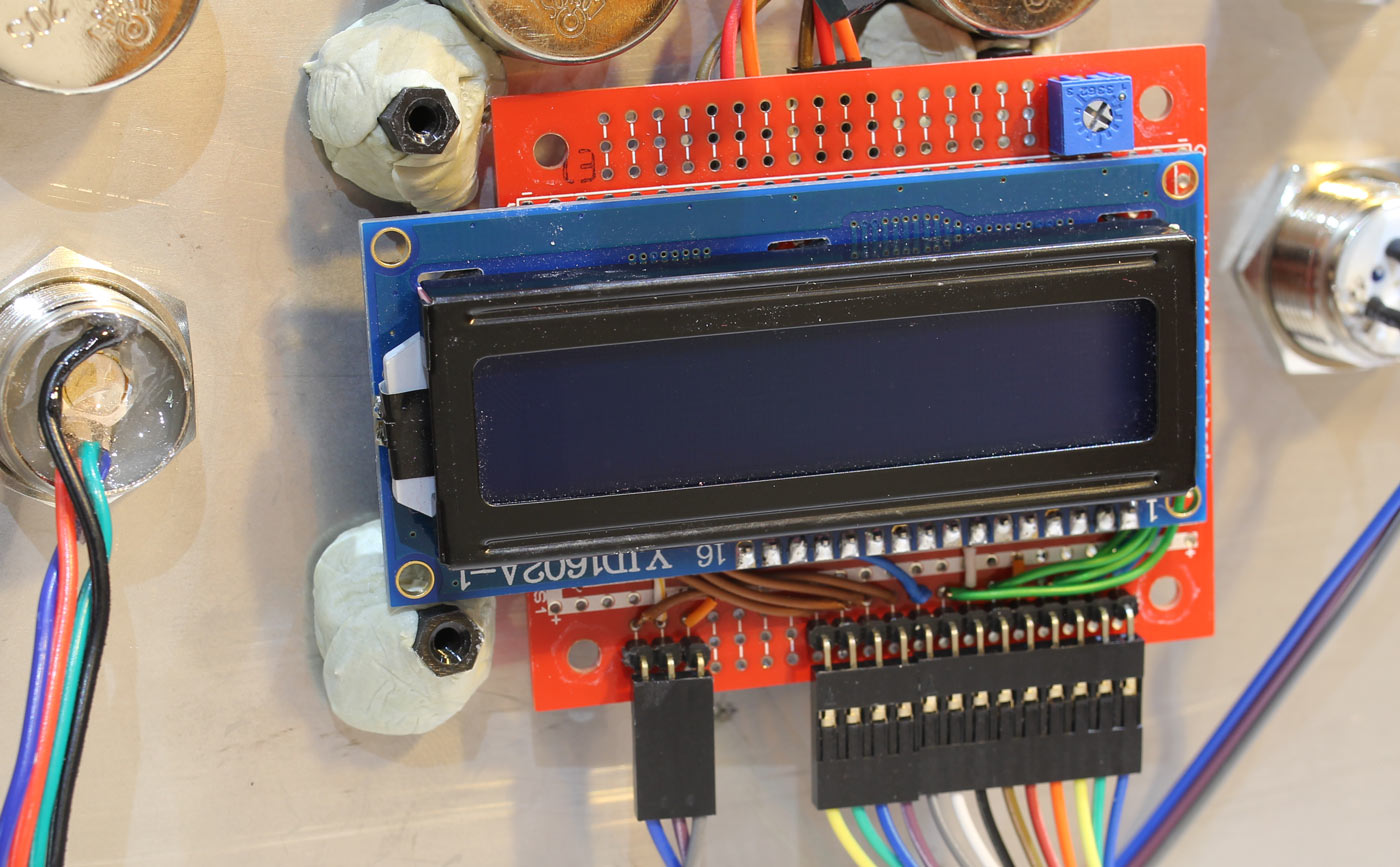
- A Control Panel which consists of: a power switch, mode switch, potentiometers for Hue, Saturation and Brightness, a 16×2 character LCD module and a large RGB LED,
- Many pieces of RGB LED Flexistrips wired around the desk.
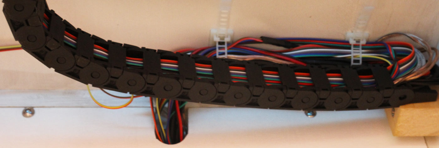
Because the control panel is located in a slide out drawer, the umbilical between it and the control board runs through a flexible channel.
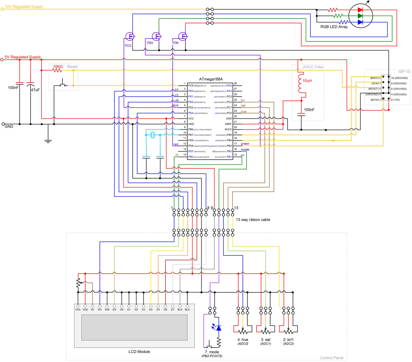
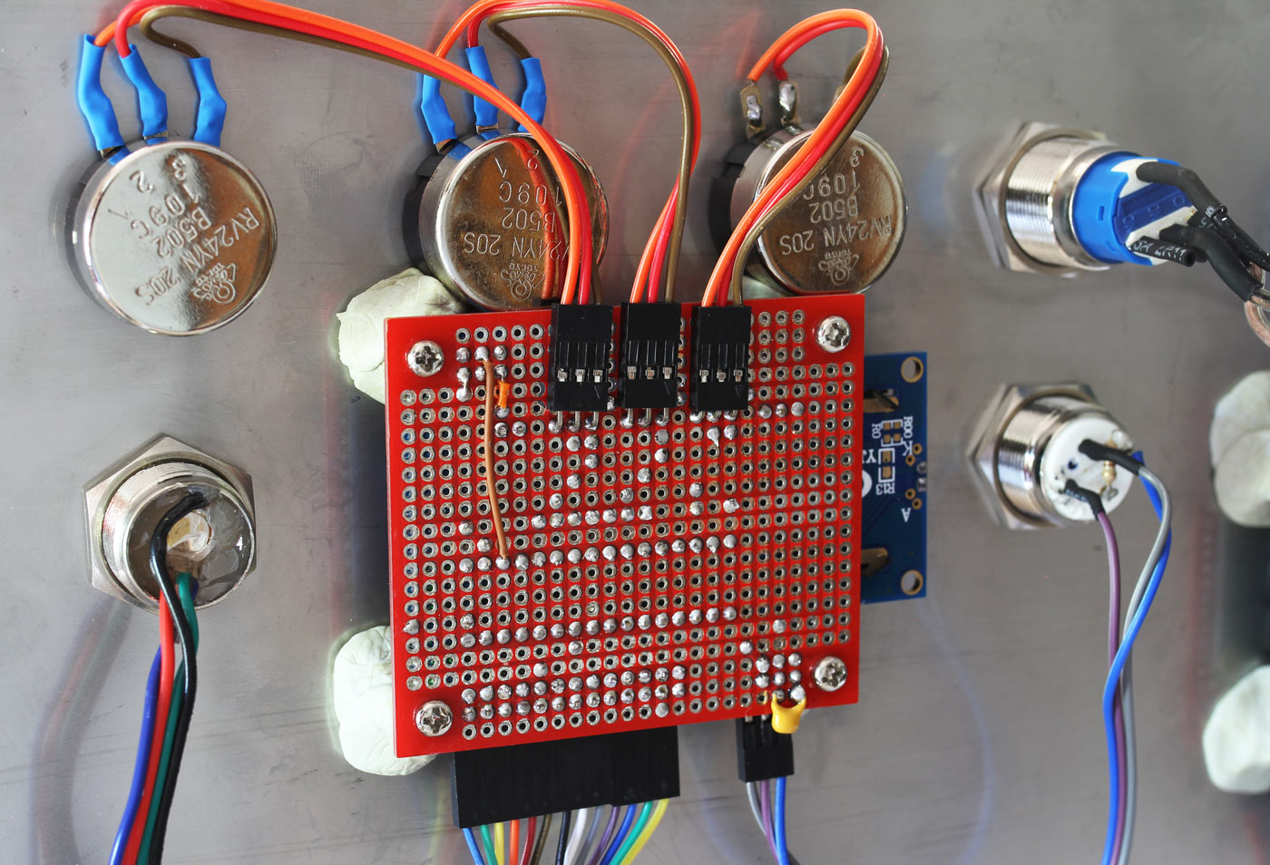
The Circuit
The current being pushed through the LEDs is a lot more than the microcontroller can handle so we use 32A MOSFETS to do the switching. These are controlled by the PMW output of PD6 (OC0A), PB3 (OC2A) and PD3 (OC2B).
The ATMega168A has 6 Analogue inputs. We use 3 of these for the hue, saturation and brightness controls.
Firmware Source Code
I won’t go into the firmware source code in detail, but it is available using the download link below:
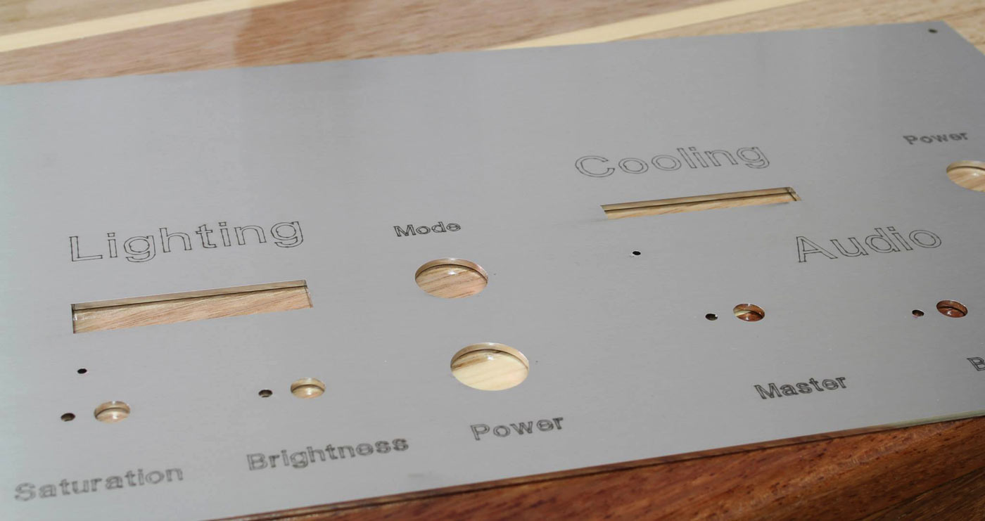
Building the Control Panel
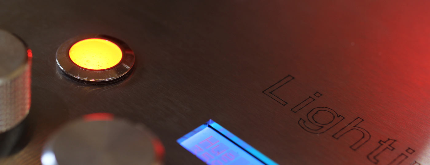
The control panel is a piece of stainless steel that was laser cut and etched. Getting it laser cut was well worth it, but the etched letters didn’t come out as nice as I expected. I was told the laser used was perfect for cutting, but was too powerful for etching letters.
A 16×2 character LCD module is mounted on a Small Prototyping Board then attached to the back of the panel using nylon standoffs. The standoffs are affixed to the panel using an epoxy based putty, the type that you knead, mould into place then allow to set.
The large LED on the left side of the panel was made by knocking the mechanism out of a 19mm pushbutton switch. A 3W RGB LED was then placed into the cavity with a mixture of epoxy resin and titanium dioxide. The titanium dioxide was used to make the resin cloudy and disperse the light.
Wiring up the LEDs
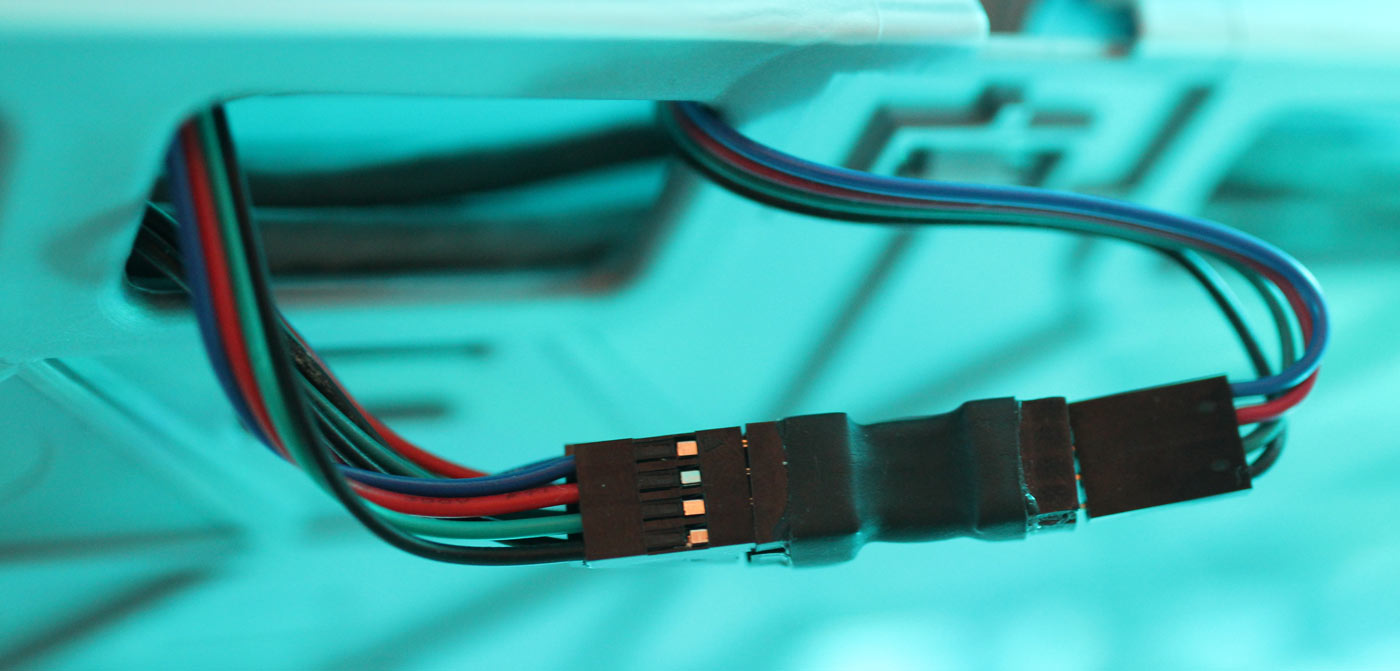
I wired up the LEDs using a ribbon cable made specifically for that purpose. This just means it had the right thickness (22AWG) and the right colours. I wanted the wiring to be easy to maintain and extend, so I created a set of n-way adapters that would allow me to branch off from a central bus.
These we made by cutting down Stacking headers, soldering them together, then sealing them with dual wall, glue lined heatshrink tubing.
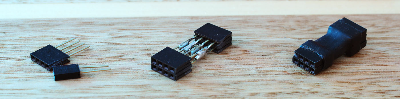
The 4 way ribbon cables are connected to the adapters using DuPont male connectors.
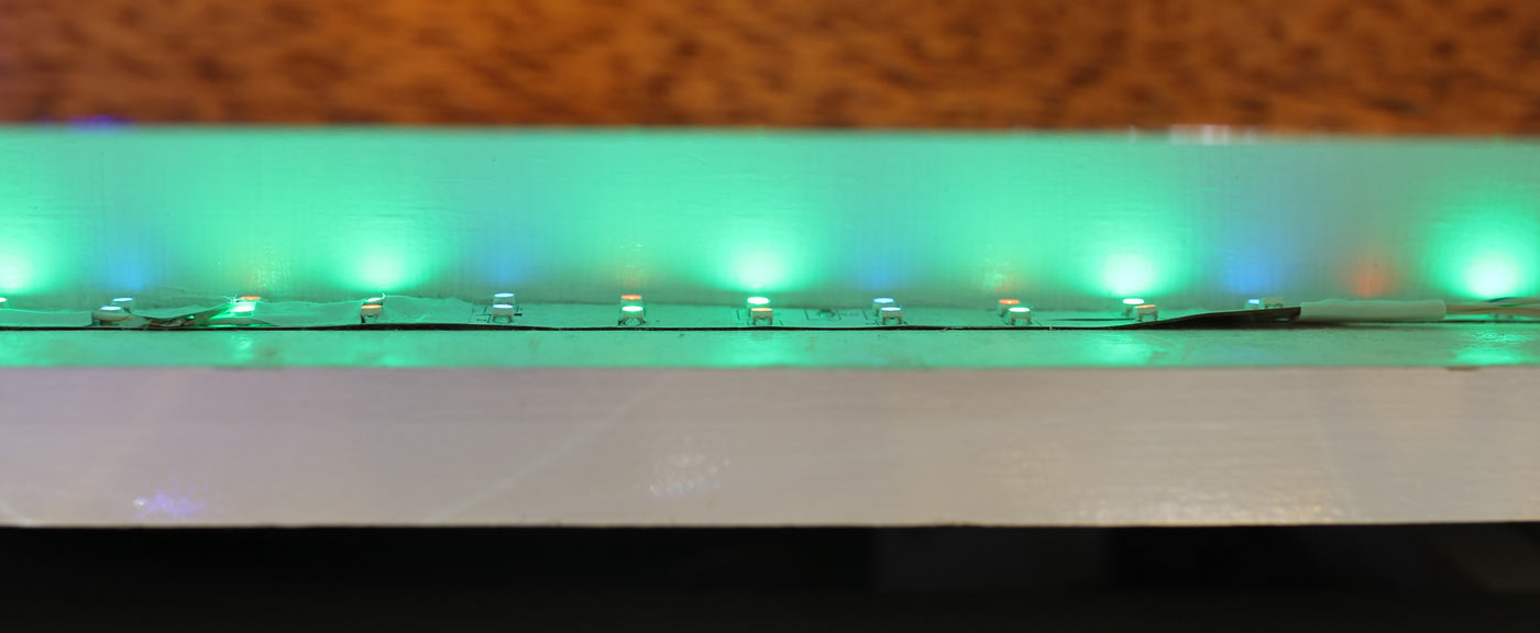
The individual colours in the RGB LED Flexistrips need to mix to form the desired colour. This can be done by placing a diffuser over them or placing them so the colours spread, reflect and mix.
The photo below shows where the desktop meets the left pedestal. This can be seen in the bottom left of the photo at the top of this post. The pedestal is recessed here, allowing the LEDs to bounce of 3 glossy white surfaces.
If you have any questions, please use the comments section below.
Sharing is caring, so if you liked this post, please share it on your favourite social platform.

