Dimming an incandescent bulb is easy. Simply adjust the current down using a potentiometer and you are done. Dimming an LED is another story entirely. When you reduce current through an LED there are unintended consequences like color shifts and dropouts. A better way is to use Pulse Width Modulation (PWM).
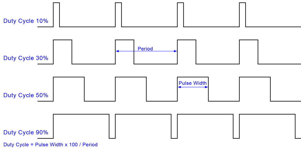
With PWM the LED is turned on and off many times per second. By adjusting the percentage of on time vs off time, the brightness of the LED can be controlled. The diagram below shows 4 PWM wave forms with varying duty cycles. The 90% duty cycle example would produce the greatest brightness whilst the 10% duty cycle will produce the least. The selected period should be sufficiently short so that a flicker isn’t noticeable.
LED dimming is not the only application of PWM. PWM is often used for controlling motors, regulating DC power, Digital to analogue conversion and much more.
Source Code Example 1
The example below produces a PWM waveform with a 20% duty cycle.
1 2 3 4 5 6 7 8 9 10 11 12 13 14 15 16 17 18 19 20 21 | #include <avr/io.h> #include <util/delay.h> #define LED_PORT PORTC #define LED_PIN 0 #define LED_off() LED_PORT&=~_BV(LED_PIN) #define LED_on() LED_PORT|=_BV(LED_PIN) int main (void) { DDRC = 0b10000000; while (1) { LED_on(); _delay_ms(2); LED_off(); _delay_ms(8); } return(0); } |
For most embedded applications, controlling PWM this way is not practical. A better approach would be to use the inbuilt PWM functionality on the ATmega168A microcontroller.
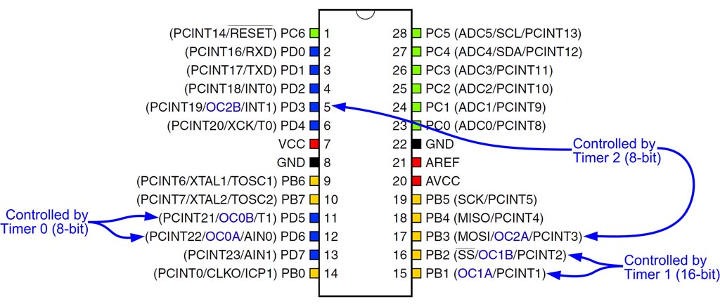
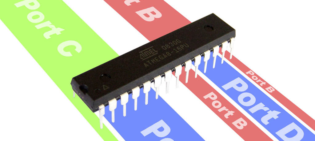
PWM output lines on ATmega168A
The ATmega168A microcontroller has 3 timers which in turn can control 6 PWM lines. Back in 2010 we did a tutorial on ATmega168 Timer Interrupts. If you are not familiar with timers, it would be useful to read this tutorial first.
On each timer, the ATmega168A has 4 modes that produce a PWM wave form. These are selected by setting the appropriate WGMx2, WGMx1 and WGMx0 bits in TCCRxA and TCCRxB.
| Mode | WGMx2 | WGMx1 | WGMx0 | Description | Top |
|---|---|---|---|---|---|
| 1 | 0 | 0 | 1 | PWM, Phase Correct | 0xFF |
| 3 | 0 | 1 | 1 | Fast PWM | 0xFF |
| 5 | 1 | 0 | 1 | PWM, Phase Correct | OCRxA |
| 7 | 1 | 1 | 1 | Fast PWM | OCRxA |
Each of the 6 PWM output lines can be set into 1 of 4 output modes. These are controlled by the COMxA1, COMxA0, COMxB1 and COMxB0 bits in the TCCRxA registers.
| COMxx1 | COMxx0 | Description |
|---|---|---|
| 0 | 0 | Normal port operation, no PWM. |
| 0 | 1 | For timer mode 3, Normal port operation, no PWM For timer mode 7, toggle output on compare match |
| 1 | 0 | Non Inverting Mode |
| 1 | 1 | Inverting Mode |
This tutorial will focus on timer mode 3 and the non inverting port mode. To use these modes we need to:
- Set the I/O lines to output mode by setting bits in the DDRx registers (see Introduction to I/O Registers)
- Select mode 3 by setting WGMx1 and WGMx0 bits in TCCRxA
- Select desired output port mode by setting the COMxA1 and COMxB1 bits in TCCRxA
- Select the duty cycle for each port by setting the OCRxA and OCRxB registers (These are split into high and low registers on the 16 bit timer)
Fun with RGB LEDs
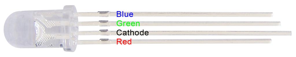
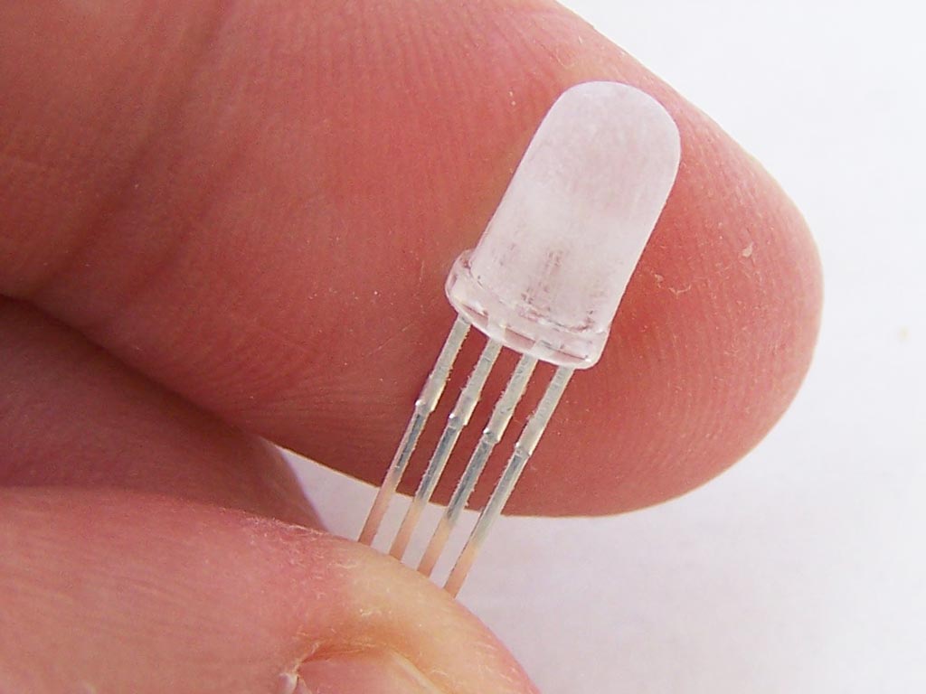
In the next example we’ll be using an RGB LED and use PWM to mix the colors together. These LEDs are really 3 different LEDs in a single epoxy package. They have a common cathode and 3 anode pins as shown below.
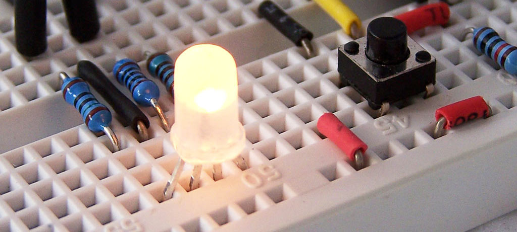
Because we’ll be mixing the colors together, we sanded the LED lightly to help diffuse the light.
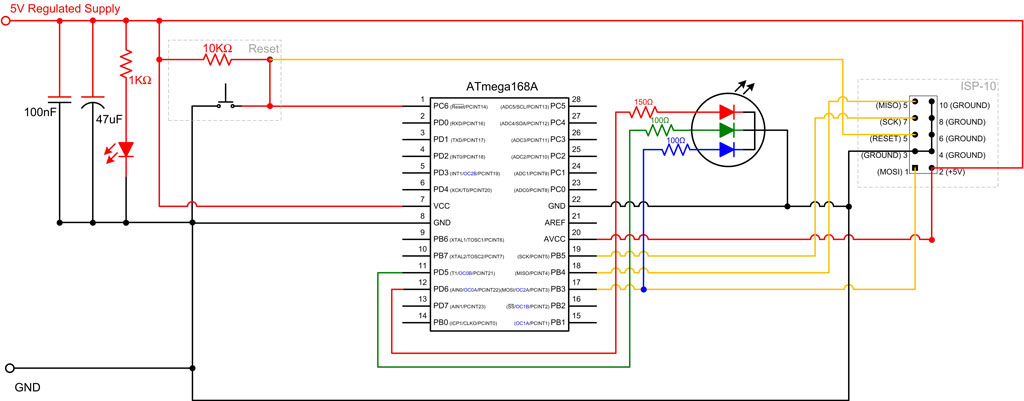
The circuit for this example is pretty simple with the RGB LED connected to OC0A, OC0B and OC2A. (PD6, PD5 and PB3). The RGB LED has different forward voltages for each color. We plugged these values into the LED Resistor Calculator and picked the nearest sizes we had on hand.
Source Code Example 2
1 2 3 4 5 6 7 8 9 10 11 12 13 14 15 16 17 18 19 20 21 22 23 24 25 26 27 28 29 30 31 32 33 34 35 36 37 38 39 40 41 42 43 44 45 46 47 48 49 50 51 52 53 54 55 56 57 58 59 60 61 62 63 64 65 66 67 68 69 70 71 72 73 74 75 76 77 78 79 80 81 82 83 84 85 86 87 88 89 90 91 92 93 94 95 96 97 98 99 100 101 102 103 104 105 106 107 108 109 110 111 112 113 114 115 116 | #include <avr/io.h> #include <util/delay.h> #include <math.h> typedef struct { float red; //0 to 1 float green; //0 to 1 float blue; //0 to 1 } SColorRGB; typedef struct { float hue; //0 to 360 float saturation; //0 to 1 float brightness; //0 to 1 } SColorHSB; int main (void) { DDRB = 0b00001000; // PB3 output DDRD = 0b01100000; // PD5 and PD6 outputs SColorHSB hsb; SColorRGB rgb; hsb.hue = 0; hsb.saturation = 1; hsb.brightness = .5; TCCR0A = _BV(COM0A1) | _BV(COM0B1) | _BV(WGM01) | _BV(WGM00); // Non inverting mode on OC0A and OC0B, Mode = Mode 3 FAST PWM TCCR0B = _BV(CS00); // No prescaling TCCR2A = _BV(COM2A1) | _BV(COM2B1) | _BV(WGM21) | _BV(WGM20); // Non inverting mode on OC2A, Mode = Mode 3 FAST PWM TCCR2B = _BV(CS20); // No prescaling while (1) { rgbFromHSB(hsb,&rgb); OCR0A = (unsigned char)(255*rgb.red); OCR0B = (unsigned char)(185*rgb.green); OCR2A = (unsigned char)(150*rgb.blue); //Uncomment and adjust the values below to adjust white balance, then transfer the value above //OCR0A=255; //OCR0B=185; //OCR1A=150; _delay_ms(10); if (hsb.hue==359) hsb.hue=0; else hsb.hue++; } return(0); } void rgbFromHSB(SColorHSB __hsb,SColorRGB * __rgb) { if (__hsb.saturation==0) { __rgb->red = __hsb.brightness; __rgb->green = __hsb.brightness; __rgb->blue = __hsb.brightness; } else { float max = __hsb.brightness; float dif = __hsb.brightness * __hsb.saturation; float min = __hsb.brightness - dif; if (__hsb.hue < 60) { __rgb->red = max; __rgb->green = __hsb.hue * dif / 60 + min; __rgb->blue = min; } else if (__hsb.hue < 120) { __rgb->red = -(__hsb.hue - 120) * dif / 60 + min; __rgb->green = max; __rgb->blue = min; } else if (__hsb.hue < 180) { __rgb->red = min; __rgb->green = max; __rgb->blue = (__hsb.hue - 120) * dif / 60 + min; } else if (__hsb.hue < 240) { __rgb->red = min; __rgb->green = -(__hsb.hue - 240) * dif / 60 + min; __rgb->blue = max; } else if (__hsb.hue < 300) { __rgb->red = (__hsb.hue - 240) * dif / 60 + min; __rgb->green = min; __rgb->blue = max; } else if (__hsb.hue <= 360) { __rgb->red = max; __rgb->green = min; __rgb->blue = -(__hsb.hue - 360) * dif / 60 + min; } else { __rgb->red = 0; __rgb->green = 0; __rgb->blue = 0; } } } |
This example cycles through all color hues: Red fading to orange then fading to yellow and so on. To achieve this we’ll use a HSB (Hue, Saturation, Brightness) color model, which is then converted to RGB values.
Although we are pumping roughly the same current for each color, some colors have greater intensity and perceived brightness than others. On lines 40-42 we multiply RGB values by a scaling factor then assign them to the corresponding Output Compare (OCRxA/B) registers. The scaling factor adjusts for the different intensities in order to preserve white balance.
Example 3 using Timer Interrupts
What do you do if you need more than 6 PWM lines? There are many solutions to this problem. Martin Ederveen, one of our customers sent us a solution that supports 3 lines, but can easily be modified for more. This solution uses timer interrupts.
1 2 3 4 5 6 7 8 9 10 11 12 13 14 15 16 17 18 19 20 21 22 23 24 25 26 27 28 29 30 31 32 33 34 35 36 37 38 39 40 41 42 43 44 45 46 47 48 49 50 51 52 53 54 55 56 57 58 59 60 61 62 63 64 65 66 67 68 69 70 71 72 73 74 75 76 77 78 79 80 81 82 83 84 85 86 87 88 89 90 91 92 93 94 95 96 97 98 99 100 101 102 103 104 105 106 107 108 109 110 111 112 113 114 115 116 117 118 119 120 121 122 123 124 125 126 127 128 129 130 131 132 133 134 135 136 137 138 139 140 141 142 143 144 145 146 147 148 149 150 151 152 153 154 155 156 157 158 159 160 161 162 | #include <avr/io.h> #include <avr/interrupt.h> #include <avr/wdt.h> #include <avr/delay.h> #include <stdio.h> #define _ms(n) (17*n) void wait(unsigned int a) //basic wait { volatile unsigned int b,c; for(b=0;b!= a; b++)for(c=0;c!= 50;c++); return; } int const bitsize=16; unsigned int one_pwm[16]; unsigned int two_pwm[16]; unsigned int three_pwm[16]; unsigned int p1=1; // Set value of point to rightmost zero in array unsigned int p2=1; unsigned int p3=1; void init_pwm () // Initialize pwm arrays { unsigned int tel=0; for (tel=1;tel<bitsize;tel++) { one_pwm[tel]=0; two_pwm[tel]=0; three_pwm[tel]=0; } one_pwm[0]=1; // Set value of rightmost bit in array two_pwm[0]=1; three_pwm[0]=1; p1=1; // Set value of point to rightmost zero in array p2=1; p3=1; return; } unsigned char port_write=0b00000000; unsigned int bitje=0; ISR(SIG_OUTPUT_COMPARE1A) { if (one_pwm[bitje]==1) { port_write |= (1<<0);} else {port_write &= ~(1<<0);} if (two_pwm[bitje]==1) { port_write |= (1<<1);} else {port_write &= ~(1<<1);} if (three_pwm[bitje]==1) { port_write |= (1<<2);} else {port_write &= ~(1<<2);} bitje++; if (bitje>=bitsize) {bitje=0;} PORTB=port_write; return; } void ioinit (void) { DDRC = 0b11000111; //1 = output, 0 = input PORTC = 0b00111000; //Enable pin 5, 4 and 3 internal pullup DDRB = 0b11111111; //1= output, 0 = input PORTB = 0b00000111; //Set PB pins 0, 1 and 2 to high } #define BTUP() (bit_is_clear(PINC,4)) #define BTDOWN() (bit_is_clear(PINC,5)) #define SWITCH() (bit_is_clear(PINC,3)) int main(void) { TIMSK1 = _BV(OCIE1A); //Enable Interrupt Timer/Counter 1,Output Compare A TCCR1B = _BV(CS11) | _BV(WGM12); //Clock/8, 0.000008 secs/tick, Mode=CTC OCR1A = 16; // SIG_COMPARE1A triggered every 0.000008*16 Seconds init_pwm(); sei(); ioinit(); //lcd_init(); unsigned int maxdelay=1; unsigned int thisport=1; while (1) { if (SWITCH()) // Button for other color control has been pushed { thisport++; if (thisport>3) {thisport=1;} // Note: only 3 ports in use _delay_ms(maxdelay*4); } if (BTUP()) // Button for pwm increase has been pushed { switch (thisport) { case 1: if (p1<bitsize) { one_pwm[p1]=1; p1++; } break; case 2: if (p2<bitsize) { two_pwm[p2]=1; p2++; } break; case 3: if (p3<bitsize) { three_pwm[p3]=1; p3++; } break; default: break; } _delay_ms(maxdelay); } if (BTDOWN()) // Button for pwm decrease has been pushed { switch (thisport) { case 1: if (p1>0) { p1--; one_pwm[p1]=0; } break; case 2: if (p2>0) { p2--; two_pwm[p2]=0; } break; case 3: if (p3>0) { p3--; three_pwm[p3]=0; } break; default: break; } _delay_ms(maxdelay); } //char buffer[16]; //sprintf(buffer, "%2d %2d %2d P%1d",p1,p2,p3,thisport); //lcd_goto(0); //lcd_puts(buffer); _delay_ms(maxdelay); } } |

Please correct your BLUE wire (blue LED lead). You have it going to ground.
Thanks for spotting that one. All fixed now.
I connected every thing as you described, i added one LCD. When i pressed the button the LCD value is double incremented. What was the problem?
3 example not working
Hello there, I’m wondering if you could help me out? Is it possible to connect ATmega168p to a PIR sensor for an air compressor to actuate inflatable components?
Firstly thanks for writing this great tutorial I found it very helpful.
I know this post is a bit old but I have a question. When I setup fast PWM using my timers the PWM seems to work and I can display and cycle various colours.
But when I assign OCR0A or OCR0B a value of 0 (zero) the LED is still very dimly lit.
Any idea if I am doing something wrong?